Prism Central is the brain of a Nutanix environment. It holds your VM templates, categories, networking and microsegmentation, disaster recovery configuration, licensing, Kubernetes platform, and a long list of service configurations that took real time to build. If a natural disaster, a power failure, or a bad day in …
Read More
A few months ago I wrote about why identity has become the new perimeter, and how building real resilience for Active Directory and Entra ID is one of the most underappreciated security investments most organizations can make. The response I got back, almost universally, was some version of the same question: "I agree …
Read More
If you are standing up Cohesity Data Protect against a Nutanix environment, one of the first decisions you make also turns out to be one of the stickiest: do you register Prism Element or Prism Central as your source? The choice shapes how much you can manage from one place, how you select what to protect, and how …
Read More
If you are moving a virtual Firepower Management Center off VMware, the part that keeps people up at night is not the deployment. It is whether every policy, object, and managed FTD comes back exactly as it was. The good news: a clean backup and restore preserves your configuration and your FTD connectivity, as long as …
Read More
If you have a Cisco Modeling Labs appliance in your lab or running on a piece of dedicated hardware, you have probably noticed two browser warnings every time you log in. CML ships with self-signed certs on both the main web UI and the Cockpit management UI, and your browser will complain about both. Cisco publishes an …
Read More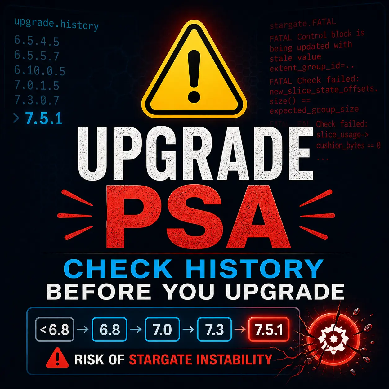
You read the release notes cover to cover before every upgrade, right? This one almost caught me. I was prepping a cluster for an upgrade to AOS 7.5.1 when a known issue in the release notes gave me pause. A quick look at the upgrade history confirmed the cluster was squarely in the affected population, and the upgrade …
Read More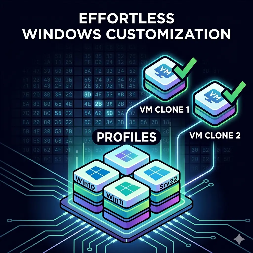
If you have ever cloned a Windows VM on Nutanix and watched five identical machines come up with the same hostname, the same SID, and a domain join you have to redo by hand, you already know why guest customization matters. For years my workflow involved hand-rolling an unattend XML file for each new template, version …
Read More
If you are a network engineer who has ever stared down a change window and wished you could test the exact topology before touching production, this post is for you. I want to walk through why Cisco Modeling Labs (CML) has become one of the most used tools in my day to day, and how it has shaped the way I approach …
Read More
There's a not-so-quiet crisis unfolding in organizations across the country. It's making headlines, driving water cooler conversations, and even finding its way to the dinner table. The cost of hardware is climbing. Lead times are stretching. And the quotes your team received last month? They may already be obsolete. …
Read More
Fair warning, this one's a bit longer than usual, so grab a cup of coffee or your favorite adult beverage and settle in. Last year I wrapped up my DC recap by saying "I look forward to seeing you next year in Chicago," and here we are. Nutanix .Next 2026 brought us back to the Windy City, McCormick Place, and a week …
Read More


